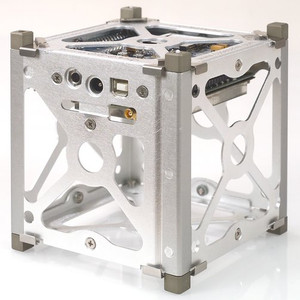
CubeSat Kit™ Chassis Walls
Pumpkin Space Systems
Precision constructed from Al 5052-H32 and plated according to the CubeSat Design Specification (CDS), each Plate Assembly is secured to the Chassis Walls via four M3 flathead stainless-steel screws. By selecting an appropriately-sized Chassis Walls, you can build a hybrid sheetmetal + machined aluminum CubeSat structure, or attached "solid" structural elements to your CubeSat Kit™ structure.
A Base Plate Assembly forms one end of a CubeSat Kit™ structure -- typically, the end with the Motherboard Module (MBM) C&DH subsystem. This plate supports cutouts for RBF pin guide, Power & USB for pre-flight operations, two separation springs and up to two separation switches on opposite corners.
A Cover Plate Assembly includes four corner feet. Options include separation plungers in the feet, and additional separation switches in the feet. A Large-Aperture Cover Plate Assembly includes a central cutout of 88mm diameter in addition.
A Payload Adapter Plate is often paired with a Payload Cover Plate Assembly, with a machined aluminum user payload located between them.
The CubeSat Kit ADCS Payload Walls are used in conjunction with two Payload Adapter Plates and one Payload Cover Plate Assembly, these three pieces can be mounted on an MAI-100/200 ADCS along with a CubeSat Kit™ Chassis Walls and Base Plate Assembly to result in an overall 3U-length CubeSat structure with an MAI-100/200 ADCS roughly in the center.
| Parameter | Value |
|---|---|
| Material | Al 5052-H32 |
| Lead time | Quote for info |
| Type | Flight Hardware |
Precision constructed from Al 5052-H32 and plated according to the CubeSat Design Specification (CDS), each Plate Assembly is secured to the Chassis Walls via four M3 flathead stainless-steel screws. By selecting an appropriately-sized Chassis Walls, you can build a hybrid sheetmetal + machined aluminum CubeSat structure, or attached "solid" structural elements to your CubeSat Kit™ structure.
A Base Plate Assembly forms one end of a CubeSat Kit™ structure -- typically, the end with the Motherboard Module (MBM) C&DH subsystem. This plate supports cutouts for RBF pin guide, Power & USB for pre-flight operations, two separation springs and up to two separation switches on opposite corners.
A Cover Plate Assembly includes four corner feet. Options include separation plungers in the feet, and additional separation switches in the feet. A Large-Aperture Cover Plate Assembly includes a central cutout of 88mm diameter in addition.
A Payload Adapter Plate is often paired with a Payload Cover Plate Assembly, with a machined aluminum user payload located between them.
The CubeSat Kit ADCS Payload Walls are used in conjunction with two Payload Adapter Plates and one Payload Cover Plate Assembly, these three pieces can be mounted on an MAI-100/200 ADCS along with a CubeSat Kit™ Chassis Walls and Base Plate Assembly to result in an overall 3U-length CubeSat structure with an MAI-100/200 ADCS roughly in the center.